Electric test meters
|
|
|
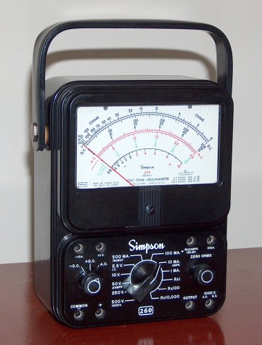
The meters we use for testing circuits have been around for many years. The meter to the right was bought from salvage in the mid 60s. There is no date on it so it is anybody's guess what its age is.
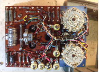
Meters like this were the standard of the industry until the digitals came along. As you can see in the view on the right, they had very complicated wiring and many components. These meters were often repaired and parts replaced. They were worth the repair because of the high cost of the meter. These meters did not suffer fools gladly. If you did not use care when handling and using these meters they would would fail catastrophically and the smoke would come out. (Electric parts run on smoke because if the smoke comes out they no longer work). The analog gauge itself was somewhat delicate and could be easily damaged. I have some nostalgia for these meters because the needle movement was sometimes easier to read and understand than the digitals. Not enough to go back to them though. |
|
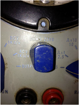
All these meters are manually ranged. What this means is, say you were wanting to check voltage. You believe the circuit is 120 volts. You set the meter for voltage and set the range for 200v because the meter gauge would read toward the center of the field. This could lead to damage to the meter if the voltage was actually 440v.
|
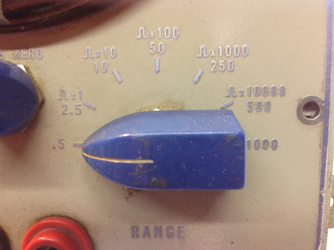
The ohmmeter is also manually ranged. Note the switch on the left. It is a range switch. If the meter is set to the ohm setting, the switch can be set to ohms X1 and the meter is zeroed with the zero adjust dial (lower left) while the leads are shorted together.
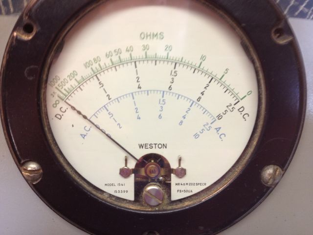
If a larger resistance is expected, you could set to ohms X 10, 100, 1000 or 10,000 then zero at the chosen range.
The part that is to be tested is then placed between the meter probes and the resistance is read on the gauge. There are sometimes fuses installed on these meters to protect them, however the fuse does not always work. The most common failure is caused by leaving the meter in ohms and placing the probes on a voltage source. This will usually damage the meter massively. |
The digital meter
|
|
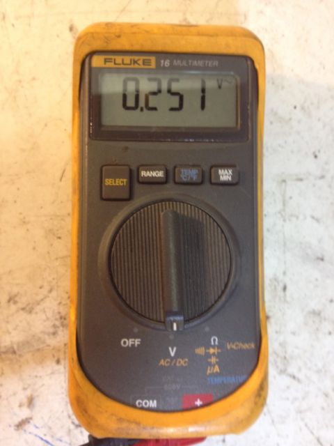
The digital meter became widespread in the 1980s. They offered a more robust design because they had no delicate dial. However, if anything they were easier to damage than analog meters. The electronics were not up to the abuse meters can be subject to. They were protected by fuses, however they were not always effective. For HVAC use, I have found that if a meter has a fuse, the meter is not well protected by its circuitry. Also, the fuses are usually odd sizes and hard to find. So, what happens when you have a blown fuse, no replacement and the work day is not done. You bypass the fuse. Then you make a mistake and blow the meter.
A meter may be very accurate and easy to use, but if it is broken it is of no use. The first meter I used that protected itself was the Fluke 16. I have owned 2 of these meters and the only reason I have the second one is that I crushed the first one. The meter is the most important tool you have. It must be robust, accurate and easy to use.
A meter may be very accurate and easy to use, but if it is broken it is of no use. The first meter I used that protected itself was the Fluke 16. I have owned 2 of these meters and the only reason I have the second one is that I crushed the first one. The meter is the most important tool you have. It must be robust, accurate and easy to use.
Below is a series of videos on meters and how they are used
The insulation tester is a form of ohmmeter used for checking the quality of the insulation of motor windings.
Most ohmmeters use a low voltage from the meter's battery to send power thru the windings to determine the resistance to the body of the motor.
The insulation tester does the same thing but uses a higher voltage such as 250, 500, or 1000 volts to put more pressure on the insulation. They are most valuable to determine insulation condition compared to an earlier test. They are commonly used in industrial motors to determine when to replace the motor to avoid down time.
The video below shows how it works.
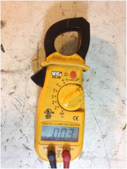
When you are using the clamp ammeter, small amp draws used to be inaccurate. So, in order to get a more accurate reading, We would wrap the wire to the component around the jaws of the meter 10 times or use a device that had the 10 wraps placed in series with the circuit. With newer meters, the accuracy has been increased to 1/100 amp. When using the digital meter, the accuracy is not depended on the 10 wire wrap. The only need for this device is for very small amp draws. The video below covers a test of this component.
What is a True RMS meter
The True RMS meter has become more common in the HVAC industry in the last few years. So, what does true RMS mean? RMS means "Root Means Square". I am sure everyone now understands completely!
For a simple explanation we need to understand the AC voltmeter.
This meter must read an average voltage (or amperage) due to the varying voltage level of the 50 to 60 cycles per second (hertz) of the AC voltage.
This works fine until we test solid state components.
Some (not all) solid state components use power differently. They often use varying pulses of power or have reverse pulses from capacitors. This may result in different readings of cycles per second (hertz) than the standard 50-60.
These meters may not always read accurately on these loads.
The True RMS rated meters are designed to account for these variations.
When we are checking loads such as variable speed blowers, these type of meters are usually necessary.
The video below is a comparison of 3 meters. Two of the meters are not true RMS. Two different types of loads are tested.
It will show the difference in readings.
